Decoding Squiggles Inductors and Circuit Diagrams
So, you're staring at a circuit diagram, and you see this weird squiggly line. What is that thing? It's not a fancy doodle; it's an inductor, and its symbol is crucial for understanding how circuits work. Let's unravel the mystery of this squiggle and why it matters.
The inductor symbol, that little coil-looking thing, represents a crucial electrical component. Inductors store energy in a magnetic field, and they’re essential for everything from filtering out noise in your radio to powering the giant electromagnets in junkyards.
These squiggles, representing the coiled wire of an inductor, aren't just arbitrary. They visually represent the component's function. The loops symbolize the coiled wire, which is the core structure of an inductor. This wire, often wrapped around a magnetic core, creates a magnetic field when current flows through it. Understanding the graphic representation of the inductor coil helps in deciphering the function of that part of the circuit.
But why bother with these symbols at all? Imagine trying to design a complex electronic system by drawing out every single component in realistic detail. It'd be a nightmare! Circuit diagrams, with their standardized symbols, provide a simplified yet powerful way to represent complex circuits. The inductor's graphic representation, among other component symbols, is a cornerstone of this visual language.
Historically, the development of standardized symbols for electrical components was a game-changer. It allowed engineers from different backgrounds and countries to understand each other's work. The inductor symbol, part of this standardized lexicon, evolved alongside the growing understanding of electromagnetism. Early representations might have been more elaborate, but they eventually simplified into the elegant squiggle we use today. This standardization paved the way for rapid advancement in electrical engineering and electronics.
An inductor's graphical representation on a diagram is directly tied to its real-world counterpart - a coil of wire. This coil stores energy in a magnetic field generated when electricity flows through it. This ability to store energy makes inductors vital for several applications, including filtering noise in circuits, tuning radio frequencies, and creating transformers. Without inductors, many of our modern electronic devices simply wouldn't function.
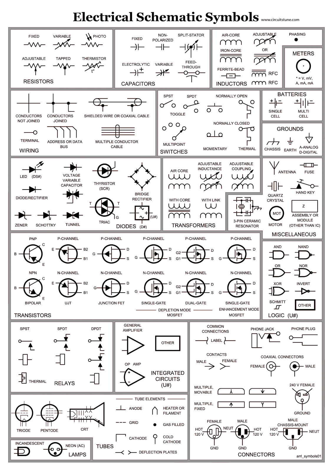
One challenge related to inductor depiction is accurately conveying the specific type of inductor on the diagram. There are various types, such as air-core, iron-core, and ferrite-core inductors, each with different properties and symbols. Representing these nuances on a schematic requires adherence to standardized symbol variations. For instance, adding two parallel lines next to the coil might indicate an iron core. Without proper symbolic representation, interpreting the inductor's characteristics and behavior within the circuit can be misleading.
Understanding the variations in inductor coil representation on a circuit diagram is crucial for accurate circuit analysis. Misinterpreting these symbols can lead to incorrect circuit behavior predictions and potential malfunctions in the actual circuit. Accurate use of these symbols is vital for efficient circuit design and troubleshooting.
Advantages and Disadvantages of Standardized Inductor Symbols
| Advantages | Disadvantages |
|---|---|
| Universal understanding | Can oversimplify complex inductor behavior |
| Simplified circuit representation | May not represent all specialized inductor types clearly |
Frequently Asked Questions:
1. What does the inductor symbol represent? - A coil of wire that stores energy in a magnetic field.
2. Why is the inductor symbol important? - It allows for easy understanding and communication in circuit diagrams.
3. How does the symbol relate to the inductor's function? - The loops symbolize the coiled wire, visually representing its energy-storing function.
4. Are there different inductor symbols? - Yes, variations exist to represent different inductor types, such as iron-core or air-core.
5. Why is standardization of these symbols important? - It ensures global understanding and collaboration among engineers.
6. What issues can arise from incorrect symbol usage? - Misinterpretation of circuit behavior, leading to faulty designs or troubleshooting.
7. What are some resources to learn more about inductor symbols? - Electronics textbooks, online circuit simulators, and component datasheets.
8. How does understanding inductor symbols benefit engineers? - It facilitates efficient circuit design, analysis, and troubleshooting.
Tips and Tricks: Always double-check the symbol key on a circuit diagram to ensure accurate interpretation of inductor symbols.
In conclusion, the seemingly simple squiggle of the inductor symbol holds significant weight in the world of electronics. This symbol is not just a graphical representation; it's a key to understanding the functionality and characteristics of inductors within a circuit. From its historical evolution to its practical importance in modern technology, the inductor symbol plays a vital role in circuit design, analysis, and communication among engineers. By understanding the nuances of this symbol, engineers can effectively utilize inductors to create and maintain the complex electronic devices we rely on daily. It's a small symbol with a big impact, and appreciating its significance is essential for anyone working with circuits. It encourages better communication, facilitates effective troubleshooting, and ultimately contributes to the advancement of electronic technology. So next time you see that squiggle, take a moment to appreciate the ingenious simplicity and power it represents.

Digital Technology Lines Diagram And Futuristic Electronic Circuit | Taqueria Autentica

What Is The Use Of Relay In Electrical Circuit at Clifford Lira blog | Taqueria Autentica

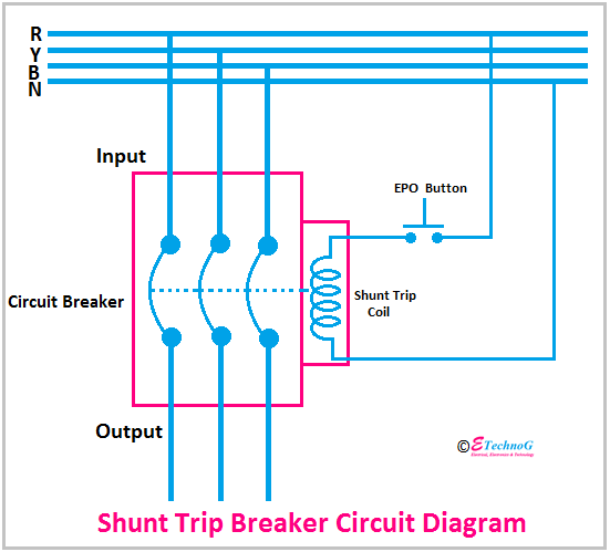
Elevator Shunt Trip Wiring Diagram | Taqueria Autentica

sabırsız logo liberal fan coil symbol Çam merkez yabancı | Taqueria Autentica

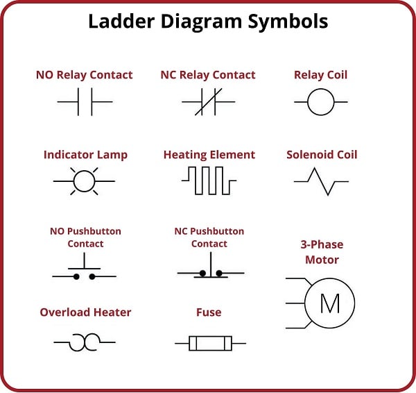
electrical diagram symbols normally open switch | Taqueria Autentica

Electronic Symbol Electromagnetic Coil Inductor Wiring Diagram Circuit | Taqueria Autentica

How to Read Wiring Diagrams in HVAC Systems | Taqueria Autentica

Electrical Circuit Symbols Vector Image Illustration Stock Vector | Taqueria Autentica

A Circuit Diagram Of An Electromagnet | Taqueria Autentica

Led Symbol Circuit Diagram | Taqueria Autentica

Solenoid Coil Schematic Symbol | Taqueria Autentica

Circuit Diagram Relay Symbol | Taqueria Autentica

How To Read PCB Schematics What The Circuit Symbols Mean | Taqueria Autentica

Relay Circuit Diagram Symbol | Taqueria Autentica

circuit diagram symbol for a coil | Taqueria Autentica