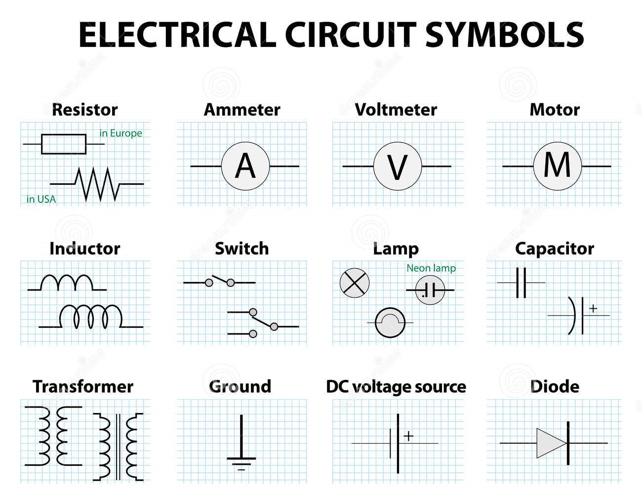
Decoding the Language of Circuits: Electronic and Electrical Symbols
Imagine trying to understand a complex conversation in a language you don't know. Frustrating, right? That's what it's like trying to decipher an electrical circuit diagram without understanding the language of electronic and electrical symbols. These symbols are the fundamental building blocks of circuit design, representing components like resistors, capacitors, transistors, and much more. Mastering them opens the door to understanding how circuits function and empowers you to design, troubleshoot, and analyze electronic systems.
Electronic and electrical symbols are standardized graphical representations of electrical and electronic components. These symbols are essential for communicating design intent in circuit diagrams, schematics, and other technical documentation. Without these standardized symbols, communicating complex electronic designs would be incredibly difficult, leading to misinterpretations and potential malfunctions.
The use of graphical symbols in electrical engineering dates back to the early days of telegraphy and power systems. As the complexity of electrical systems grew, so too did the need for standardized representations of components. Organizations like the International Electrotechnical Commission (IEC) and the Institute of Electrical and Electronics Engineers (IEEE) played crucial roles in standardizing these symbols internationally, ensuring clear communication across different engineering communities.
The importance of understanding electrical and electronic symbol representations cannot be overstated. They provide a universal language that transcends geographical and linguistic barriers, allowing engineers worldwide to collaborate effectively. Accurate interpretation of these symbols is crucial for correctly assembling circuits, troubleshooting faults, and even designing new electronic systems.
One of the major issues related to electrical and electronic symbology is maintaining consistency and staying updated with the latest standards. With the continuous evolution of technology and the emergence of new components, new symbols are constantly being developed and standardized. Keeping abreast of these changes is vital for engineers and technicians to remain proficient in reading and interpreting contemporary circuit diagrams.
A resistor, for example, is represented by a zigzag line, symbolizing its function of restricting current flow. A capacitor, used to store electrical charge, is symbolized by two parallel lines. These simple yet effective visualizations provide immediate insight into the function of each component within a circuit.
Understanding these schematic representations has several benefits. First, it allows for efficient communication between engineers. Second, it simplifies the process of troubleshooting and repairing circuits. Finally, it forms the basis for designing and developing new electronic devices and systems.
A practical action plan for mastering these symbols would involve studying standardized symbol charts, practicing reading circuit diagrams, and using simulation software to visualize circuit behavior. Online resources, textbooks, and interactive applications offer excellent platforms for learning and practice.
If you are designing a simple circuit, a checklist could include verifying correct component symbols, ensuring proper connections, and double-checking the power source configuration. This meticulous approach minimizes errors and ensures the circuit functions as intended.
Advantages and Disadvantages of Standardized Electrical Symbols
| Advantages | Disadvantages |
|---|---|
| Clear and concise communication | Requires learning and memorization |
| Universal understanding across different languages and regions | Can be complex for highly specialized components |
| Simplified troubleshooting and circuit analysis | New symbols are constantly being introduced, requiring continuous learning |
A real-world example of using these symbols is in the design of a smartphone. The intricate circuit board within the phone is designed using these symbols, guiding the placement and interconnection of every component. Another example is the electrical wiring diagram of a house, which uses symbols to represent outlets, switches, and light fixtures, helping electricians understand the wiring layout.
One common challenge is the sheer number of symbols to learn. A solution is to focus on the most frequently used symbols initially and gradually expand your knowledge. Another challenge is keeping up with evolving standards. Joining professional organizations and regularly reviewing industry publications can help address this challenge.
Frequently asked questions include: What is the symbol for a diode? What does a ground symbol represent? What is the difference between AC and DC symbols? How do I represent a transistor in a circuit diagram? Understanding the answers to these fundamental questions forms a strong foundation for understanding more complex circuit designs.
A helpful tip is to use mnemonic devices or visual associations to remember symbols. For instance, associating the capacitor symbol with two parallel plates storing charge can aid in memorization.
In conclusion, electronic and electrical symbols are the essential language of circuit design. Understanding their history, importance, and practical applications is crucial for anyone working with electronics. From simple resistors to complex integrated circuits, these symbols provide a concise and universal way to represent and communicate complex electronic designs. Mastering this symbolic language opens doors to designing, troubleshooting, and analyzing electronic systems, empowering innovation and facilitating communication across the global engineering community. Continue learning and exploring the world of electronic symbols, and you'll find yourself well-equipped to navigate the ever-evolving landscape of electronics.

Electrical and Electronics Symbols | Taqueria Autentica

Electrical Schematic Common Symbols | Taqueria Autentica

Electrical Circuit Symbols Pdf | Taqueria Autentica

Table Of Common Electronics Wiring Symbols | Taqueria Autentica
.jpg)
electronic and electrical symbols | Taqueria Autentica

Electrical Electronic Symbols A Basic Introduction with Chart | Taqueria Autentica

electronic and electrical symbols | Taqueria Autentica

Basic Important Electrical Symbols and Electronic Symbols | Taqueria Autentica

Circuit Diagram Schematic Symbols | Taqueria Autentica

electronic and electrical symbols | Taqueria Autentica

electronic and electrical symbols | Taqueria Autentica

the electrical and electronic circuit symbols are shown in gold on a | Taqueria Autentica

How To Use Schematics On Basic Electronics | Taqueria Autentica

electronic and electrical symbols | Taqueria Autentica

100 Electrical Electronic Circuit Symbols | Taqueria Autentica