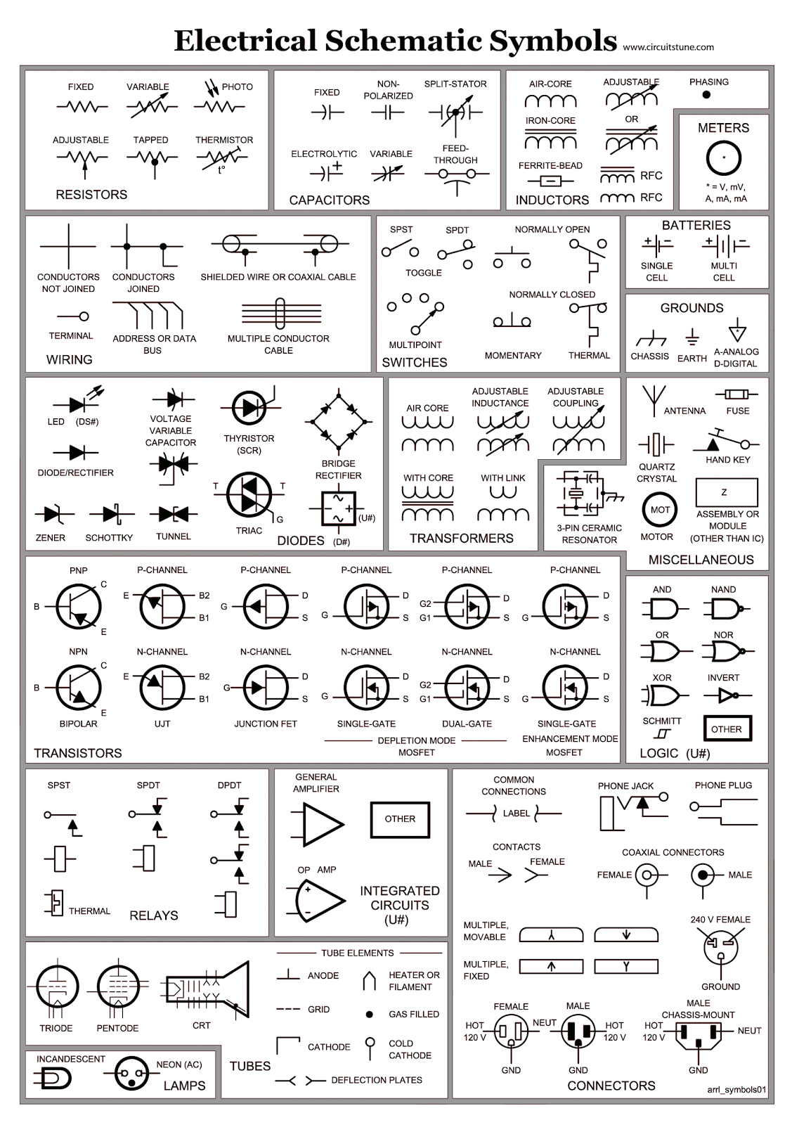
Decoding the Matrix: Understanding Electrical Schematic Switch Symbols
Ever stared at a circuit diagram and felt like you were deciphering an alien language? Those cryptic symbols, interconnected by lines, hold the key to understanding how electrical systems function. They're the language of electricity, and fluency in this language is essential for anyone working with circuits, from hobbyists to seasoned electricians. This guide will unravel the mystery of electrical schematic switch symbols, providing you with the knowledge to confidently navigate the world of circuit diagrams.
Electrical schematic switch symbols are standardized graphical representations of different types of switches used in electrical circuits. They provide a concise and universally understood way to depict the switching mechanisms within a circuit, allowing engineers and technicians to design, analyze, and troubleshoot electrical systems effectively. These symbols are essential for clear communication and accurate representation of complex electrical designs. Imagine trying to describe a complex circuit using only words – it would quickly become a tangled mess. Switch symbols offer a visual shorthand that simplifies the representation of circuit components and their connections.
The history of electrical schematic symbols is intertwined with the development of electrical engineering itself. As electrical systems became more complex, the need for a standardized system of representation became apparent. Early diagrams were often crude and varied, leading to confusion and misinterpretations. Over time, organizations like the IEEE (Institute of Electrical and Electronics Engineers) and IEC (International Electrotechnical Commission) developed standardized symbols to ensure clarity and consistency in electrical drawings. These standardized symbols have become the foundation of modern electrical schematics.
The importance of correctly interpreting and utilizing these symbols cannot be overstated. Misunderstanding a single symbol can lead to faulty circuit design, malfunctioning equipment, and even safety hazards. Accurate schematic diagrams are crucial for everything from designing simple household circuits to complex industrial control systems. They allow engineers to simulate circuit behavior, identify potential problems, and ensure the safety and reliability of electrical systems.
One of the primary challenges associated with electrical schematic switch symbols is the sheer number of different symbols. There are symbols for various types of switches, including single-pole single-throw (SPST), single-pole double-throw (SPDT), double-pole double-throw (DPDT), and many more. Each symbol represents a specific switching action, and understanding these nuances is critical for correctly interpreting a schematic. Additionally, different standards (e.g., IEEE, IEC) may have slight variations in their symbols, which can sometimes lead to confusion. Familiarizing oneself with these different standards and their respective symbols is crucial for effectively working with electrical schematics.
A single-pole single-throw (SPST) switch, represented by a simple open and closed contact symbol, controls a single circuit. A single-pole double-throw (SPDT) switch, depicted with a contact that can connect to one of two other contacts, allows switching between two different circuits. Double-pole double-throw (DPDT) switches, which control two separate circuits simultaneously, are represented with two sets of interconnected contacts.
Three key benefits of using standardized electrical schematic switch symbols are clarity, efficiency, and safety. Clarity: Standardized symbols ensure that everyone working with a schematic understands the components and their connections, regardless of their background or experience. Efficiency: Using symbols simplifies the design and analysis process, allowing engineers to quickly visualize and understand complex circuits. Safety: Accurate schematic diagrams are essential for identifying potential safety hazards and ensuring the safe operation of electrical systems. For example, using the correct symbol for a normally closed switch (which is closed by default) is critical for preventing accidental short circuits.
Advantages and Disadvantages of Standardized Switch Symbols
| Advantages | Disadvantages |
|---|---|
| Universal understanding | Initial learning curve |
| Simplified circuit representation | Potential for confusion between similar symbols |
| Improved communication among engineers | Variations across different standards (e.g., IEEE, IEC) |
Best Practices: 1. Always use the correct symbol for the specific type of switch. 2. Ensure consistency in symbol usage throughout the schematic. 3. Clearly label all components and connections. 4. Use a consistent drawing style and follow established drafting conventions. 5. Double-check your work to ensure accuracy and avoid errors.
FAQ: 1. What is the difference between SPST and SPDT switches? 2. How are momentary switches represented in schematics? 3. What is the significance of normally open and normally closed contacts? 4. How are three-way switches depicted in a schematic? 5. What are the common symbols for relays and contactors? 6. How are push buttons represented? 7. What is the difference between a switch and a circuit breaker in a schematic? 8. How are rotary switches depicted?
In conclusion, electrical schematic switch symbols are the essential building blocks of circuit diagrams. They provide a concise and universally understood language for describing the switching mechanisms within electrical systems. Mastering these symbols is crucial for anyone working with circuits, from hobbyists to seasoned professionals. By understanding the history, importance, and various types of switch symbols, you can unlock the secrets of circuit diagrams and confidently navigate the world of electrical design. The ability to interpret and utilize these symbols accurately is essential for designing safe, reliable, and efficient electrical systems. Start exploring, learning, and mastering these symbols today, and you’ll open up a whole new world of understanding about how the devices around us work.

Electrical Drawing Symbols at PaintingValleycom | Taqueria Autentica

Relay Logic Diagram Switch Symbols | Taqueria Autentica

Circuit Diagram Symbol For Switch | Taqueria Autentica

Electrical Schematic Symbol For Proximity Switch at David King blog | Taqueria Autentica

Schematic Symbol For Switch | Taqueria Autentica

Schematic Symbol For Switch | Taqueria Autentica
Hvac Schematic Diagram Symbols | Taqueria Autentica

Electrical 3 Way Switch Symbol | Taqueria Autentica

Electrical Schematic Symbols Switch | Taqueria Autentica

A Letter Designation Sl On An Electrical Drawing Indicates A | Taqueria Autentica

Electrical And Electronic Circuit Symbols | Taqueria Autentica

The Ultimate Guide to Understanding the Float Switch Schematic Symbol | Taqueria Autentica

Cat Wiring Schematic Switch Symbols Electrical | Taqueria Autentica

Electrical Schematic Switch Symbols | Taqueria Autentica

Electrical Schematic Diagram Symbols | Taqueria Autentica