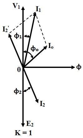
Understanding Transformer Resistive Load Phasor Diagrams
Imagine trying to understand the flow of alternating current in a circuit with a transformer and a simple resistive load. It's like trying to grasp the rhythm of a complex piece of music just by listening to it once. A phasor diagram of a transformer with a resistive load offers a visual representation, making this complex electrical behavior much clearer. It's a powerful tool for simplifying AC circuit analysis.
A phasor diagram visually represents the magnitude and phase relationship between voltage and current in an AC circuit. In the specific case of a transformer with a purely resistive load, the voltage and current are in phase. This means they reach their peak values and zero crossings at the same time. This in-phase relationship is depicted on the phasor diagram as two arrows (phasors) pointing in the same direction. The length of the arrows represents the magnitude of the voltage and current.
Historically, understanding the behavior of AC circuits was a significant challenge for early electrical engineers. The development of phasor diagrams provided a breakthrough, offering a graphical method to analyze these circuits. This paved the way for designing and optimizing more efficient power systems. Before the widespread use of computer simulations, phasor diagrams were essential tools for electrical engineers.
The importance of a transformer resistive load phasor diagram lies in its ability to simplify complex calculations. Instead of dealing with sinusoidal functions and trigonometric identities, engineers can visually represent the relationship between voltage and current. This simplified approach makes it easier to analyze circuit behavior, troubleshoot issues, and design effective power systems. The diagram is a cornerstone in electrical engineering education, providing a fundamental understanding of AC circuit principles.
One of the main issues related to understanding transformer phasor diagrams, in general, is grasping the concept of phase. Students sometimes struggle to visualize how voltage and current can be out of phase in circuits with reactive components. However, with a resistive load, this complexity is reduced, making it an ideal starting point for learning about phasor diagrams. This simplicity allows for a clearer understanding of the basic principles before moving on to more complex scenarios.
A simple example of a transformer resistive load phasor diagram would involve a single-phase transformer connected to a resistor. The primary voltage phasor is drawn as a reference. Since the load is purely resistive, the secondary voltage and current phasors are aligned with the primary voltage phasor, indicating a zero-degree phase difference. The ratio of the lengths of the primary and secondary voltage phasors represents the transformer turns ratio.
One benefit of using a phasor diagram is its ability to simplify complex calculations. Another advantage is the visual representation of phase relationships, making it easier to understand how voltage and current interact in AC circuits. Finally, phasor diagrams provide a foundation for analyzing more complex circuits with reactive components, building a solid understanding of electrical principles.
Advantages and Disadvantages of Using Phasor Diagrams
| Advantages | Disadvantages |
|---|---|
| Simplifies complex AC circuit analysis | Can be difficult to interpret for complex circuits |
| Provides a visual representation of phase relationships | Doesn't provide information about transient behavior |
| Facilitates understanding of circuit behavior | Requires understanding of phasor representation |
Frequently Asked Questions:
1. What is a phasor? A phasor is a rotating vector representing a sinusoidal quantity.
2. What is a phasor diagram? A visual representation of phasors in a circuit.
3. Why are phasor diagrams useful? They simplify AC circuit analysis.
4. What does it mean for voltage and current to be in phase? They reach peaks and zero crossings simultaneously.
5. What is the significance of a resistive load in a transformer phasor diagram? Voltage and current are in phase.
6. How does the transformer turns ratio affect the phasor diagram? It determines the relative lengths of primary and secondary voltage phasors.
7. How do phasor diagrams help in troubleshooting? They can visually pinpoint discrepancies in voltage and current relationships.
8. What is the difference between a phasor diagram for a resistive load and a reactive load? In a resistive load, voltage and current are in phase; in reactive loads, they are out of phase.
In conclusion, the phasor diagram of a transformer with a resistive load serves as a foundational element in understanding AC circuit analysis. Its simplicity and clarity allow for a visual grasp of the relationship between voltage and current, making it an invaluable tool for both students and experienced engineers. By simplifying complex calculations and providing a clear visual representation, phasor diagrams enable more effective design, analysis, and troubleshooting of power systems. Understanding these diagrams is crucial for anyone working with AC circuits and transformers. Take the time to study and practice with these diagrams to build a strong foundation in electrical engineering principles. This knowledge will empower you to design and analyze more efficient and reliable power systems.

DIAGRAM Electrical Transformer Phasor Diagram | Taqueria Autentica

Load Regulation Circuit Diagram | Taqueria Autentica

How To Draw A Phasor Diagram Physics | Taqueria Autentica
Solved Draw the phasor diagram of single phase transformer at unity | Taqueria Autentica

How To Control Voltage In Power System at Daniel Richards blog | Taqueria Autentica

Transformer ON Load Condition | Taqueria Autentica

Series Rlc Circuit Phasor Diagram | Taqueria Autentica

Pure Inductive Circuit Phasor Diagram | Taqueria Autentica

How To Draw A Phasor Diagram | Taqueria Autentica

Amazing How To Draw A Phasor Diagram For Transformer of the decade Don | Taqueria Autentica

DIAGRAM Electrical Transformer Phasor Diagram | Taqueria Autentica

Three Phase Star Delta Connection | Taqueria Autentica

What Does A Purely Resistive Circuit Mean at Felipe Rogers blog | Taqueria Autentica

Equivalent Circuit Of A Single Phase Transformer | Taqueria Autentica

What is a Pure Resistive Circuit | Taqueria Autentica