Unlocking Automation: Your Guide to PIR Controller Circuit Diagrams
Ever walked into a dark room and wished the lights would magically turn on? Or perhaps you're tired of leaving lights on all night, wasting precious energy and money? A Passive Infrared (PIR) sensor, coupled with a well-designed controller circuit, can solve these problems and unlock a world of automation possibilities. Understanding the PIR controller schematic diagram is the key to harnessing this power.
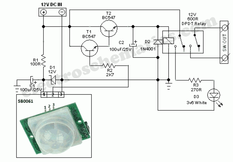
A PIR controller schematic diagram is essentially a roadmap for building a circuit that uses a PIR sensor to detect motion and trigger an action, typically turning a light on or off. Think of it as the blueprint for a small, self-contained robotic brain that watches for movement and reacts accordingly. This seemingly simple technology has a wide range of applications, from basic motion-activated lighting to more complex security systems.
The beauty of a PIR controller circuit lies in its simplicity and efficiency. It's a low-cost solution that can significantly reduce energy consumption by ensuring lights are only on when needed. This not only saves you money but also reduces your environmental impact. Furthermore, PIR sensors are readily available and the circuits are relatively easy to understand and assemble, even for beginners.
While the core functionality of a PIR controller remains consistent, variations exist in the circuit design depending on the specific application. Some diagrams may incorporate features like adjustable sensitivity, time delays, and even daylight sensors to further refine the system's behavior. Exploring different PIR controller schematic diagrams allows you to customize the circuit to perfectly match your needs.
Delving into the specifics of a PIR controller schematic diagram reveals a fascinating interplay of components. The heart of the circuit is the PIR sensor itself, which detects infrared radiation emitted by warm objects, such as humans or animals. This sensor is connected to a control circuit, typically based on a simple integrated circuit (IC) or a microcontroller. The control circuit processes the sensor's output and activates a relay or transistor, which in turn switches the load (e.g., a light bulb) on or off.
The history of PIR technology traces back to the development of infrared detectors in the early 20th century. Over time, these detectors evolved into the compact and affordable PIR sensors we see today. The earliest PIR-based motion detectors were primarily used in security systems, but their affordability and ease of use quickly led to wider adoption in residential and commercial lighting applications.
One common issue with PIR controllers is false triggering, often caused by rapid temperature changes or interference from other sources of infrared radiation. Understanding the circuit diagram and proper placement of the sensor can help mitigate these issues.
A simple example of a PIR controller application is an automatic porch light. When someone approaches the door, the PIR sensor detects their motion, triggering the controller to turn on the light. After a pre-defined time delay, if no further motion is detected, the controller switches the light off automatically.
Benefits of using PIR controller schematics: 1) Energy saving by activating lights only when needed, 2) Enhanced security by detecting intruders, 3) Increased convenience by automating lighting control.
Creating a PIR-based lighting system involves several steps: 1) Choose a suitable PIR controller schematic, 2) Gather the necessary components, 3) Assemble the circuit following the diagram, 4) Test and adjust the system.
Advantages and Disadvantages of PIR Controller Schematics
| Advantages | Disadvantages |
|---|---|
| Energy efficient | Potential for false triggers |
| Cost-effective | Limited range of detection |
| Easy to implement | Sensitivity to temperature changes |
Frequently Asked Questions:
1. What is a PIR sensor? - A sensor that detects infrared radiation from moving objects.
2. How does a PIR controller work? - It processes the sensor's output and activates a switch.
3. What are the common applications? - Motion-activated lighting, security systems.
4. What are the benefits of using a PIR controller? - Energy saving, security, convenience.
5. How to troubleshoot false triggering? - Adjust sensitivity, reposition the sensor.
6. Where can I find PIR controller schematics? - Online electronics forums, datasheets.
7. What components are needed? - PIR sensor, IC, relay, power supply.
8. Can I build my own PIR controller? - Yes, with basic electronics knowledge.
Tips and tricks: Consider the sensor's field of view, adjust sensitivity to avoid false triggers, and use a suitable power supply.
In conclusion, PIR controller schematic diagrams provide a powerful and accessible way to harness the benefits of motion-sensing technology. Whether you're looking to improve your home's security, reduce your energy bills, or simply add a touch of automation to your life, understanding these diagrams is the first step. By carefully selecting the right schematic and following the instructions, you can create a customized solution that perfectly meets your needs. From simple porch lights to complex security systems, the possibilities are limited only by your imagination. Embrace the power of automation and start exploring the world of PIR controller schematics today! So, dive in, get your hands dirty, and unlock the potential of efficient and automated systems with PIR technology. You'll be amazed at the difference it can make in your daily life and your wallet.

HC SR501 PIR Motion Sensor Module Pinout Datasheet Details Components | Taqueria Autentica

Pir Sensor Schematic Symbol | Taqueria Autentica

Pir Sensor Schematic Diagram | Taqueria Autentica

pir controller schematic diagram | Taqueria Autentica

PIR Sensor Security Light Switch | Taqueria Autentica

Motion Sensor Circuit Diagram | Taqueria Autentica

pir controller schematic diagram | Taqueria Autentica

DIAGRAM Wiring Diagram For Pir Sensor | Taqueria Autentica

Simple Pir Motion Sensor Circuit Diagram | Taqueria Autentica

Power Saver Circuit Diagram using PIR | Taqueria Autentica

Relay Use Motion Sensor at Sherri Donato blog | Taqueria Autentica

Motion Sensor Schematic Diagram | Taqueria Autentica

Wiring Diagram Pir Light Switch Schematic And Wiring Diagram | Taqueria Autentica

Pir Controller Schematic Diagram | Taqueria Autentica

pir controller schematic diagram | Taqueria Autentica