Unlocking Circuits: Understanding Electrical and Electronics Symbols
Have you ever looked at a circuit diagram and felt overwhelmed by the cryptic symbols scattered across the page? Understanding electrical and electronic symbols is crucial for anyone working with circuits, from hobbyists to seasoned engineers. These symbols represent various components and connections, forming a universal language that simplifies complex electrical designs and facilitates communication between engineers worldwide.
Imagine trying to describe a complex circuit using only words – it would be a confusing and inefficient process. Electrical and electronic symbols provide a concise and standardized way to represent circuit elements, making it easier to design, analyze, and troubleshoot electrical systems. This visual language allows engineers to quickly grasp the functionality of a circuit without needing lengthy descriptions.
The history of electrical and electronic symbols is intertwined with the development of electricity itself. As electrical systems became more complex, the need for a standardized symbolic representation grew. Early symbols were often crude representations of the components they represented, evolving over time into the more abstract and standardized forms we use today. This standardization is vital for ensuring clear communication and avoiding misinterpretations that could lead to faulty circuit design or dangerous situations.
The importance of understanding these symbols cannot be overstated. Whether you're building a simple circuit or designing a complex electronic device, knowing what each symbol represents is fundamental. This knowledge allows you to accurately interpret circuit diagrams, troubleshoot issues, and build functional electronic systems. Misinterpreting a symbol can lead to incorrect circuit connections, malfunctioning devices, and even safety hazards.
One of the main issues related to electrical and electronic symbols is the potential for confusion due to variations or outdated symbols. While standardization efforts have greatly improved consistency, it's still possible to encounter older or less common symbols. Therefore, it's essential to refer to reliable resources and standards to ensure accurate interpretation. Familiarizing yourself with different symbol standards, such as IEC and ANSI, can further enhance your understanding.
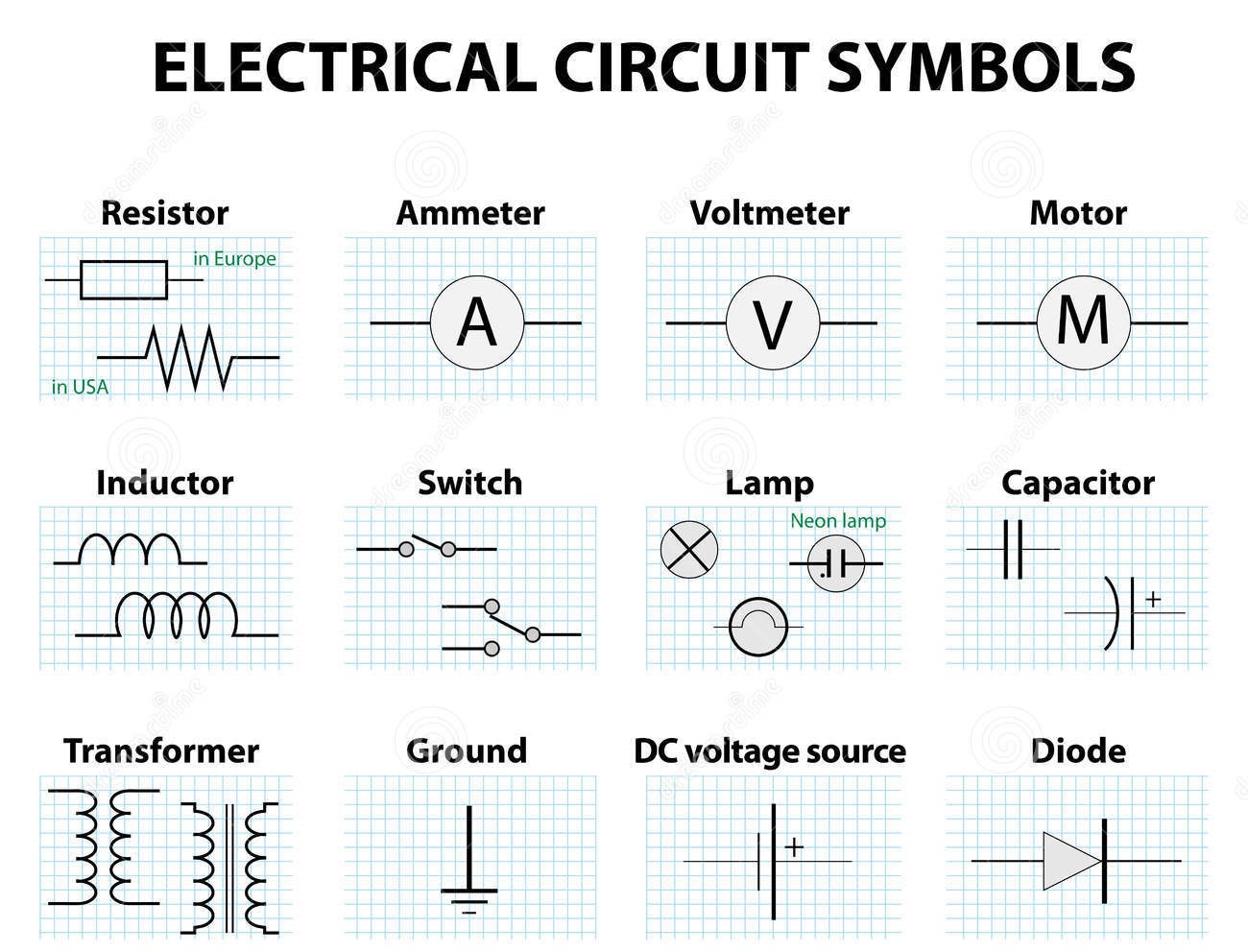
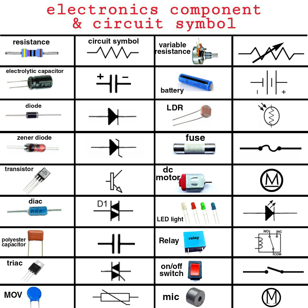
Electrical symbols represent various components like resistors, capacitors, and transistors. Electronic symbols represent integrated circuits, logic gates, and microcontrollers. A simple example is the resistor symbol, a zig-zag line, indicating resistance to current flow. A capacitor is represented by two parallel lines.
Benefits of using standardized symbols include efficient communication, easier troubleshooting, and simplified circuit design. For example, using the standard symbol for a diode immediately tells anyone looking at the diagram that the component allows current flow in only one direction. This eliminates the need for lengthy explanations and improves overall clarity.
To master these symbols, start with basic components and gradually move to more complex ones. Use online resources, textbooks, and circuit simulation software to practice interpreting and creating diagrams. Building simple circuits based on diagrams is an excellent way to solidify your understanding.
A simple checklist: identify all components, verify connections, and double-check for any unfamiliar symbols.
Step-by-step guide: obtain the circuit diagram, identify the power source, trace the current path, and analyze the function of each component.
Recommendations: All About Circuits website, The Art of Electronics book.
Advantages and Disadvantages of Standardized Electrical and Electronics Symbols
| Advantages | Disadvantages |
|---|---|
| Universal understanding | Potential for confusion with outdated symbols |
| Simplified communication | Requires initial learning and familiarization |
| Efficient circuit design | Can be overwhelming for beginners |
Best practices: 1. Use standard symbols. 2. Keep diagrams clean and organized. 3. Label all components. 4. Indicate polarity. 5. Use consistent line weights.
Real examples: 1. Resistor in a light bulb circuit. 2. Capacitor in a power supply. 3. Transistor in an amplifier. 4. Diode in a rectifier circuit. 5. Integrated circuit in a computer.
Challenges: 1. Inconsistent symbols. Solution: Refer to standards. 2. Complex diagrams. Solution: Break them down into smaller sections. 3. Unfamiliar symbols. Solution: Consult resources. 4. Misinterpretations. Solution: Double-check. 5. Software compatibility. Solution: Use standard software.
FAQ: 1. What is a resistor? 2. What does a capacitor do? 3. What is a diode? 4. How does a transistor work? 5. What is an integrated circuit? 6. How do I read a circuit diagram? 7. Where can I find electrical symbols? 8. What are the different types of electrical diagrams?
Tips: Use color-coding for clarity. Practice drawing diagrams regularly. Refer to datasheets for specific component information. Join online communities to learn from others. Explore interactive simulations to visualize circuit behavior.
In conclusion, electrical and electronics symbols are the bedrock of circuit design and analysis. They provide a universal language that facilitates communication, simplifies complex designs, and promotes efficient troubleshooting. While challenges such as varying standards and potential for misinterpretation exist, adhering to best practices, utilizing reputable resources, and continuous learning can overcome these obstacles. Mastering these symbols empowers you to unlock the intricacies of electronic circuits and opens doors to endless possibilities in the world of electronics. Whether you are a budding engineer or a seasoned professional, a deep understanding of electrical and electronic symbology is an invaluable asset in navigating the exciting landscape of circuit design and analysis. Continue learning, exploring, and pushing the boundaries of your understanding. The world of electronics awaits your innovation.

Basic Electrical And Electronics Symbols | Taqueria Autentica

Electrical Symbols in PDF for Free Download | Taqueria Autentica
.jpg)
Symbols For Electronic Schematics | Taqueria Autentica

Electrical Symbols Word Doc Format | Taqueria Autentica

Symbols For Electrical Schematics | Taqueria Autentica

Electrical Wiring Symbols Pdf | Taqueria Autentica

Full Intruduction About Electrical and Electronic Symbols | Taqueria Autentica

Electrical And Electronic Devices And Symbols | Taqueria Autentica

100 Electrical Electronic Circuit Symbols | Taqueria Autentica

Circuit Symbols Stock Illustrations | Taqueria Autentica

Electrical Circuit Symbols Pdf | Taqueria Autentica

Printable Electrical Symbols Chart | Taqueria Autentica

Basic Schematic Symbols Chart | Taqueria Autentica

Electronic Schematic Symbols Pdf | Taqueria Autentica

Electrical Schematic Common Symbols | Taqueria Autentica