Unveiling the Magic: Understanding PIR Sensor Circuitry
Have you ever wondered how those automatic lights in your hallway or the motion-activated security system work? The secret lies within a tiny but powerful component: the Passive Infrared (PIR) sensor. These ingenious devices detect changes in infrared radiation, effectively sensing movement and triggering a response. Understanding the PIR sensor internal circuit diagram is key to appreciating their functionality and unlocking their potential in various applications.
The heart of a PIR sensor lies in its ability to detect variations in infrared radiation emitted by objects. This is achieved through a specialized lens and a pair of pyroelectric sensors. When a warm body moves across the sensor's field of view, the infrared radiation pattern changes, creating a differential voltage between the two pyroelectric elements. This voltage is then amplified and processed by the sensor's internal circuitry, ultimately triggering an output signal.
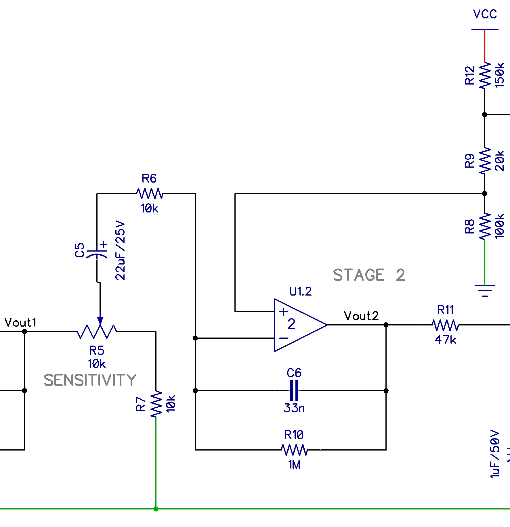
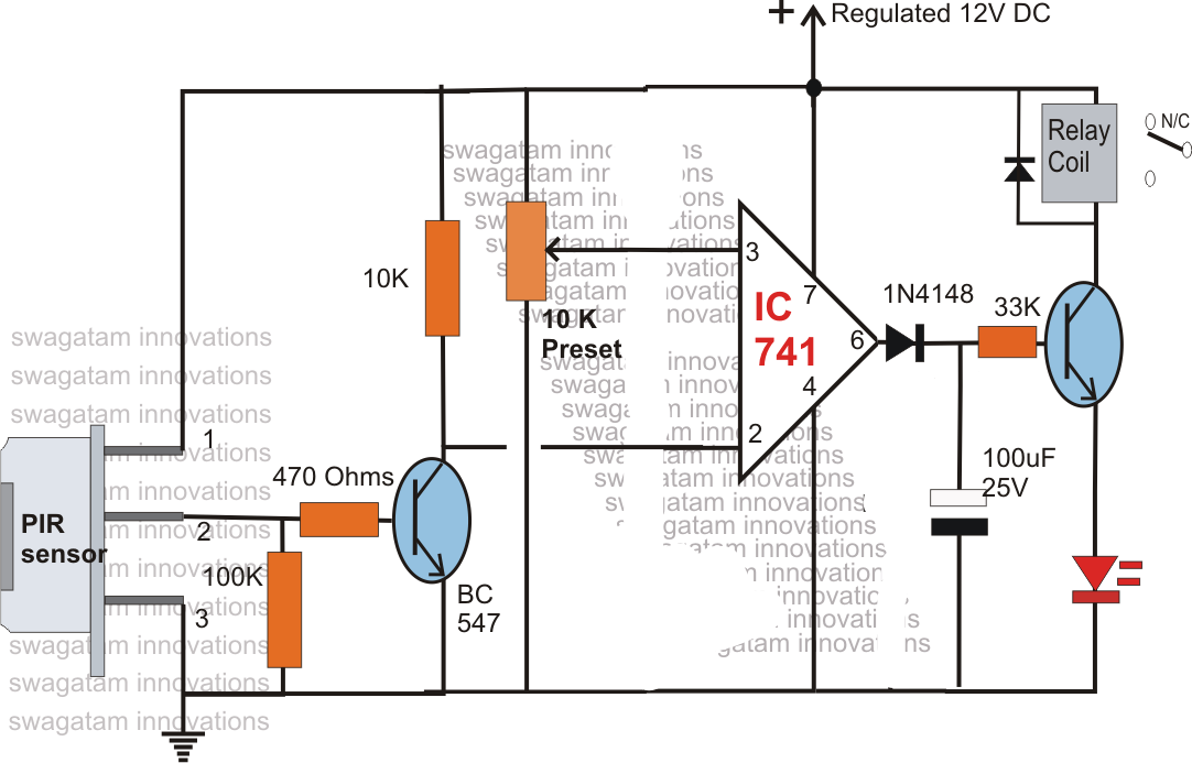
Delving deeper into the PIR sensor schematic reveals a carefully designed network of components working together. The pyroelectric sensors are connected to a preamplifier, which boosts the weak voltage signal generated by the sensors. This amplified signal is then fed into a comparator, which compares the signal to a reference voltage. If the difference exceeds a predefined threshold, the comparator triggers an output signal, indicating motion detection.
The history of PIR sensors traces back to the development of pyroelectric materials. These materials exhibit a unique property: they generate an electrical charge when exposed to changes in temperature. This discovery paved the way for the creation of PIR sensors, which utilize this property to detect changes in infrared radiation, a proxy for heat and movement. Over the years, advancements in microelectronics have miniaturized and refined PIR sensor technology, making them more sensitive, reliable, and affordable.
The significance of understanding PIR sensor internal circuitry extends beyond mere curiosity. It empowers makers, engineers, and hobbyists to troubleshoot, modify, and even design custom PIR sensor circuits tailored to specific needs. For example, adjusting the sensitivity of a PIR sensor requires an understanding of the potentiometer within the circuit that controls the comparator threshold. Similarly, modifying the timing characteristics involves adjusting the components responsible for the sensor's output pulse duration.
A typical PIR sensor circuit includes components like resistors, capacitors, operational amplifiers (op-amps), and a MOSFET for switching the output. Understanding the role of each component is crucial for analyzing the circuit's behavior. For example, the resistors and capacitors form timing circuits that determine the sensor's sensitivity and response time.
Benefits of understanding the PIR sensor circuit diagram include: 1) Troubleshooting – identifying faulty components; 2) Customization – modifying sensitivity and timing; 3) Integration – designing custom circuits for specific applications.
Troubleshooting a PIR sensor involves checking the power supply, testing the pyroelectric sensors, and verifying the output signal. If the sensor is not triggering, the problem could lie in a faulty power supply, damaged sensors, or incorrect circuit configuration.
Advantages and Disadvantages of Using PIR Sensors
| Advantages | Disadvantages |
|---|---|
| Low power consumption | Can be triggered by non-human sources (pets, sunlight) |
| Relatively inexpensive | Limited range and field of view |
| Easy to integrate into circuits | Performance can be affected by environmental factors (temperature, humidity) |
Best practices: 1) Use proper shielding to avoid false triggers; 2) Consider the sensor's range and field of view; 3) Choose the appropriate power supply; 4) Use proper grounding techniques; 5) Test the circuit thoroughly.
Challenges and Solutions: 1) False triggers due to pets – adjust sensitivity; 2) Limited range – use multiple sensors; 3) Environmental factors – choose sensors with temperature compensation.
FAQs: 1) What is a PIR sensor? 2) How does a PIR sensor work? 3) What are the applications of PIR sensors? 4) How to troubleshoot a PIR sensor? 5) What is the range of a PIR sensor? 6) How to adjust the sensitivity of a PIR sensor? 7) How to integrate a PIR sensor into a circuit? 8) What are the different types of PIR sensors?
Tips and tricks: Ensure the Fresnel lens is clean and free of obstructions. Experiment with the sensor's placement and orientation to optimize its performance.
In conclusion, the PIR sensor's internal circuit diagram serves as a roadmap to understanding its inner workings. From the pyroelectric sensors that capture infrared radiation to the comparator that triggers the output signal, each component plays a crucial role. By understanding this intricate circuitry, we can not only troubleshoot and customize existing PIR sensor circuits but also design new applications that leverage their unique capabilities. The future of motion detection is bright, and with a deeper understanding of PIR sensors, we can unlock their full potential and create smarter, more responsive environments. Explore the resources available online, delve into the schematics, and experiment with PIR sensor circuits. You'll be amazed by the possibilities that unfold when you unravel the magic of these ingenious devices.

Motion Sensor Trigger Switch at Norma Gray blog | Taqueria Autentica

Motion Sensor Circuit Diagram | Taqueria Autentica

Motion Sensor Led Light Circuit Diagram | Taqueria Autentica

Pir Sensor Internal Circuit Diagram | Taqueria Autentica

Pir Sensor Internal Circuit Diagram | Taqueria Autentica

Wiring Diagram For Motion Sensor Light | Taqueria Autentica

Arduino Motion Sensor Circuit Diagram | Taqueria Autentica

DIAGRAM Torque Sensor Block Diagram | Taqueria Autentica

Pir Sensor Internal Circuit Diagram | Taqueria Autentica

Pir Sensor Pin Diagram | Taqueria Autentica

pir sensor internal circuit diagram | Taqueria Autentica

Motion Detector Light Wiring | Taqueria Autentica

Pir Sensor Internal Circuit Diagram | Taqueria Autentica